Our Control System
Contents
What is a control system?
There are two types of control systems, open loop and close loop. A control system regulates the behavior of a system using control loops. There is a process variable, which is what is being controlled, and a setpoint which is the desired value of the process variable. In open loop systems, the value of the process variable is ignored when determining control actions. An example of this is a drying machine. Let us assume the drying machine has a moisture sensor, and the amount of moisture would be the process variable. We want the dryer to dry the clothes completely, so the setpoint would be 0. The control action would be turning the machine on and off. In an open loop system, we would ignore the process variable, and just set a timer for how long run the dryer(we would try and calculate it beforehand so the setpoint would be met), so the control action would be independent of the process variable. In a closed loop system, the control action of turning the dryer off would not occur until the process variable reaches the setpoint(completely dry). To do this, the dryer would constantly need to update and check the state of the process variable, thus creating a feedback loop getting feedback from the moisture sensor until the setpoint is reached.
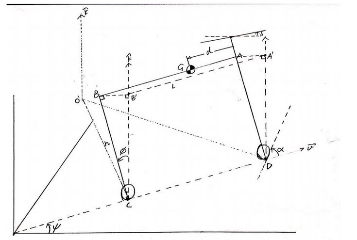
Physical Model of the Bike[1]
In the diagram,
- G is the center of mass
- AD is the front handlebar
- C and D are the contact points between the two wheels and the ground
- Φ is the lean angle
- ψ is the yaw angle
- δ is the steer angle
- α is the between the front wheel and line CD
- v is the forward velocity of the bike, assumed to be constant
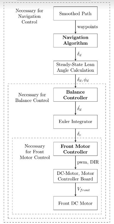
From the perspective of control systems, the behavior that must be controlled is the movement of the bike as modeled above. It must be ensured that the bike both balances and follows the desired path. The execution of this control is divided into three cascading controllers, with higher level controllers piping their output for lower level controllers as input. The three controller, arranged from high level to low level are -
- Navigation Controller: This tries to get the bike to follow the desired path, by calculating the desired steer angle the bike needs to take to move along that path
- Balance Controller: This takes the desired steer angle, and tries to calculate the rate at which the steer angle should be changed to achieve the required lean angle for the bike to be able to steer in that angle without falling over. This rate of change of steer angle is continually converted to a commanded steer angle by Euler integration.
- Front Motor Controller: This actually powers the front motor to make he front wheel move in the direction as commanded by the Balance controller
The three controllers together, therefore, take a desired path as input, and change the angle of the front wheel in order to make the bike follow that path without falling over. The structure of the controllers is illustrated below
The Navigation Controller takes in a path in the form of (x,y) waypoints and uses the navigation algorithm[2] to calculate the desired steer angle. If a bicycle is turning, it needs to both steer and lean to avoid falling. The desired lean angle (Φd) is calculated from the desired steer angle (δd) by the formula
Here, v represents the speed of the bike [m/s], g is acceleration due to gravity [m/s2], and l is the distance between the front and rear wheels of the bike.
Balance Controller
The Balance controller takes 5 inputs: desired steer angle (δd) and desired lean angle (Φd) from the Navigation controller, current lean angle (Φ), current rate of change of lean angle (Φ'), and current steer angle (δ). Currently we use these variables in a linear controller to calculate the required rate of change of steer angle (δd'). The formula is:
where k1, k2, k3 are constants. The choice of these constants must be optimized to give the best performance for the controller. The value of (δd') is piped to the Euler integrator to give the commanded steer angle (δc)
Front Motor Controller
The Front Motor controller uses a PD (Proportional-Derivative controller) to calculate a value called total_error with the following formula:
This value is then converted to a direction and magnitude that dictates the actions of the front motor.
References
- ↑ Shihao Wang. Dynamic model derivation and controller design for an autonomous bicycle. Dec 18 2014. https://drive.google.com/file/d/0ByhwjGqiUphVWmRETXZHb1ZZSlU/view
- ↑ Cornell Autonomous Bicycle Team Fall 2017 Report https://drive.google.com/file/d/17YwGG2BGJ9p5w1mTUVXPzjvbqffEhQMY/view?usp=sharing


