Difference between revisions of "The New Bike"
(→General) |
|||
| Line 2: | Line 2: | ||
==General== | ==General== | ||
| − | + | [[File:Bike_dimensions.png|200px|thumb|right|General Dimensions]] | |
| − | [[File: | + | [[File:Frame.jpg|200px|thumb|left|The Frame of the New Bicycle]] |
| − | [[File: | + | The frame is a ***cm KTM Trento with serial number ******. |
| − | The wheels are 27 inches in diameter. The planned tires will be 27 inch road bike tires. | + | |
| + | The wheels are 27 inches in diameter. The planned tires will be 27 inch road bike tires. General dimensions for the bike can found in the image to the right. | ||
==Mechanical Components== | ==Mechanical Components== | ||
Revision as of 22:07, 23 February 2021
This is the next platform of the Cornell Autonomous Bicycle Team. It is intended to be a more stable, reliable, and versatile platform than The Old Bike. The bike is still largely in the design phase, so wiki sections are limited to the current state of the bike.
Contents
General
The frame is a ***cm KTM Trento with serial number ******.
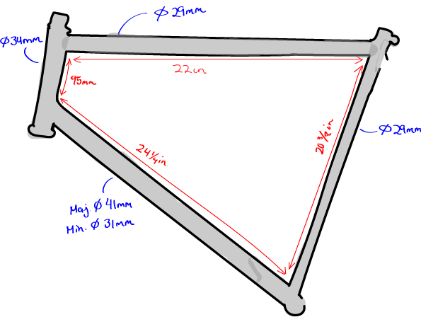
The wheels are 27 inches in diameter. The planned tires will be 27 inch road bike tires. General dimensions for the bike can found in the image to the right.
Mechanical Components
There are a few major structural components being planned for the new bike. The new bike will feature a clear enclosure within the middle of the bike that will hold and display the bike's electronics. In order to facilitate this structure, we created two key joints that adhere themselves to the frame of the bike to provide necessary support. Similar to The Old Bike, this bike will also feature an enclosure for its front motor that will sit on the top of the bike on the same axis as the fork. The connection to the bike, however, will differ from that of the Old Bike. One thing we are trying to fix in this new design is the need for more permanent fixtures, such as welding.
Top Frame Joint
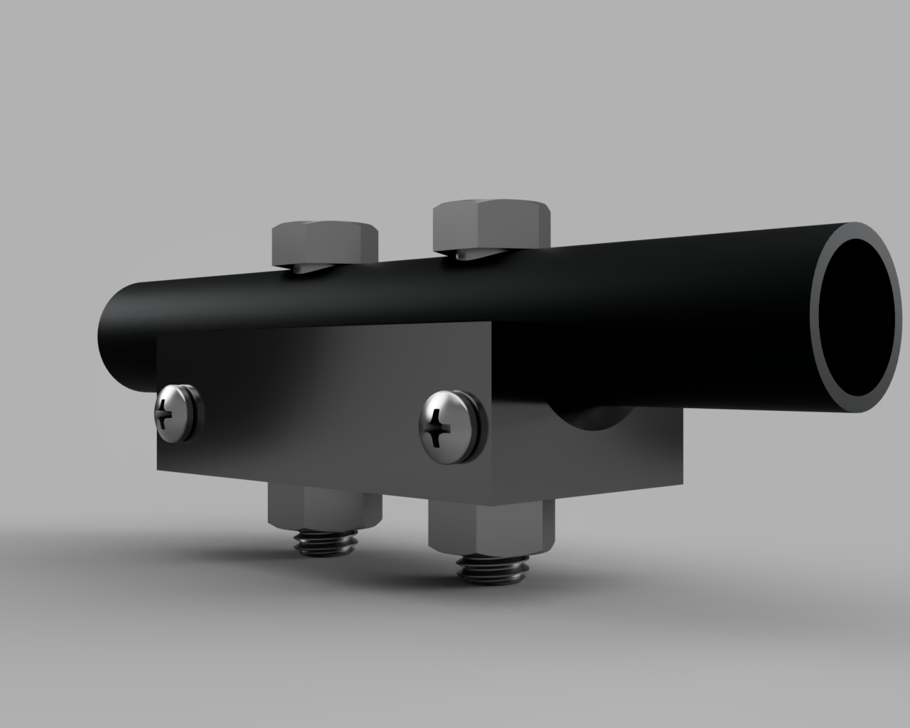
As stated in the intro, the frame joint acts to suspend the clear panes that will encase the electronics in the center of the bike. The top frame joint specifically is made for the rounded surface at the top of the bike. It is made up of 4 major components: a machined piece of aluminum or other light metal, a piece of rubber that sits between the bike and the machined component, two hex head screws, and two nuts to match.
Near the bottom edge of the aluminum there are four threaded holes (two on either side) that indicate where the aluminum will attach to the clear panes. The rubber sits directly on top of the curved edge of the aluminum. It is meant to provide grip strength so that the component does not slip out of place. There are two 9/16" holes on top that propagate through the entire design and the bike frame itself that make space for the bolts and nuts to compress all the components to the bike frame. We plan to have between 2-3 top frame joints will line the top tube.
Bottom Frame Joint
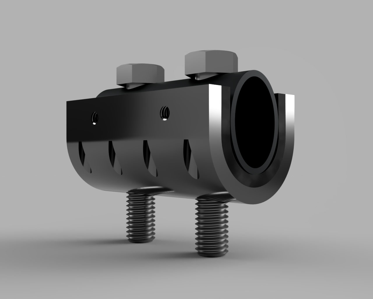
The bottom frame joint has an identical function as the top frame joint. However, the bottom frame joint's geometry differs from it because the cross section of the bottom tube is elliptical. This presented a unique design challenge that we had to work around. We ended up on settling on an idea that combines 4 different parts together: 2 flat plates, a hemispherical piece, and rubber.
In order to match the elliptical shape of the bottom tube these parts are screwed together as seen in the image. There exist larger holes on the surface of the hemispherical piece to make room for screw heads, and there exist threaded holes that cut through half of the flat pieces. Near the top edge of the flat plates there are threaded screw holes for attachment to the clear planes. The rubber again acts as a way to grip the components to the frame and prevent slip. Just like the top frame joint, there are two 9/16" holes made in both the frame, rubber, and hemispherical piece to make room for the bolts and nuts to compress the system to the bike frame. 2 Bottom frame joints will be used to hold the clear plane.
Front Motor Assembly
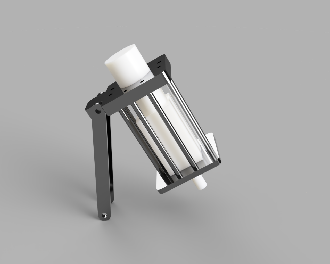
The Front Motor Assembly protects the front motor and aligns the motor with the axis of the fork. It is made up of 2 pieces of aluminum, 8 spacers, 2 rods, a coupling (not pictured), and a connection to the bike (not pictured). The connection to the bike has a short rod on one side to connect to the coupling and a larger threaded component on its opposite end.
The rods on the back of the assembly connect to the bike and the top plate to provide support for the weight of the system. The spacers act as protection for the motor, by caging it in, in the case of falls.
Fixtures To The Plexiglass
To house the components in the plexiglass, we are planning to displace the components with the use of spacers to the middle of the enclosure. This is in order to reduce the electronics from harm in the case of fall. In addition, we plan to include visco-elastic material in the connections of the spacers in order to reduce the vibration that migrates to the components. In order to hold the camera, we also plan to add a boom-like assembly to the sides of the plexiglass.
Everything Camera
The camera will be mounted somewhere between 3-5 feet above the bike. In order to achieve this we will place boom-like assemblies on the side of the bike that will connect to one another above the bike. On the connection, we plan to mount a camera clamp of some kind. We will take advantage of the standard threaded hole that exists on the bike's camera to utilize this. This will allow for us to easily change the angle of the camera, if necessary. We suspect a lot of vibration to occur while the bike is moving and thus are planning to implement visco-elastic materials within our support system for the camera. We are also considering creating a snap-fit case or bar-like enclosure (like the front motor) for the camera to protect it during falls.


