Difference between revisions of "The New Bike"
(→Electronics Panel) |
|||
| (12 intermediate revisions by 2 users not shown) | |||
| Line 1: | Line 1: | ||
This is the next platform of the Cornell Autonomous Bicycle Team. It is intended to be a more stable, reliable, and versatile platform than [[The Old Bike]]. The bike is nearly complete with completion expected in Spring 2022. | This is the next platform of the Cornell Autonomous Bicycle Team. It is intended to be a more stable, reliable, and versatile platform than [[The Old Bike]]. The bike is nearly complete with completion expected in Spring 2022. | ||
| − | ''LAST UPDATE FALL 2021'' | + | |
| + | '''''LAST UPDATE - FALL 2021''''' | ||
[[File:CombinedFull.png|500px|thumb|right|Full rendering of new bicycle]] | [[File:CombinedFull.png|500px|thumb|right|Full rendering of new bicycle]] | ||
| Line 14: | Line 15: | ||
The “Brain” is defined by its contents: the electronics. It is composed of 4 clamp-like components, 2 sheets of acrylic, and 2 panels for the electronics to sit. The clamp-like components connect to the edges of the bike diamond in order to give the acrylic sheets points to connect to in order to enclose the frame. The electronics, once situated onto their corresponding panels, will be attached with velcro to the acrylic sheets. Similar to the brain, the “Body” is defined by its function, in this case, the handling of actuation and vision on the bike. The body is composed of 2 main intertwining assemblies. One centered around the motor and the other around the camera. | The “Brain” is defined by its contents: the electronics. It is composed of 4 clamp-like components, 2 sheets of acrylic, and 2 panels for the electronics to sit. The clamp-like components connect to the edges of the bike diamond in order to give the acrylic sheets points to connect to in order to enclose the frame. The electronics, once situated onto their corresponding panels, will be attached with velcro to the acrylic sheets. Similar to the brain, the “Body” is defined by its function, in this case, the handling of actuation and vision on the bike. The body is composed of 2 main intertwining assemblies. One centered around the motor and the other around the camera. | ||
| + | |||
=Mechanical Components= | =Mechanical Components= | ||
| Line 33: | Line 35: | ||
===Bottom Frame Bracket=== | ===Bottom Frame Bracket=== | ||
[[File:BottomFrameBracketRender.png|200px|thumb|left|Bottom Frame Joint]] | [[File:BottomFrameBracketRender.png|200px|thumb|left|Bottom Frame Joint]] | ||
| − | [[File:BottomFrameBracketReal.jpg|200px|thumb|right|Bottom Frame Joint]] | + | [[File:BottomFrameBracketReal.jpg|200px|thumb|right|Bottom Frame Joint Final]] |
The bottom frame joint has an identical function as the top frame joint. However, the bottom frame joint's geometry differs from it because the cross-section of the bottom tube is elliptical. This presented a unique design challenge that we had to workaround. We ended up settling on an idea that combines 4 different parts together: 2 flat plates, a hemispherical piece, and rubber. | The bottom frame joint has an identical function as the top frame joint. However, the bottom frame joint's geometry differs from it because the cross-section of the bottom tube is elliptical. This presented a unique design challenge that we had to workaround. We ended up settling on an idea that combines 4 different parts together: 2 flat plates, a hemispherical piece, and rubber. | ||
| Line 54: | Line 56: | ||
===Motor Connection point=== | ===Motor Connection point=== | ||
[[File:MotorConnectionPointRender.png|200px|thumb|left|Motor connection point]] | [[File:MotorConnectionPointRender.png|200px|thumb|left|Motor connection point]] | ||
| + | |||
| + | The Motor Connection as seen below is the main mechanism that connects the motor encasement legs to the top tube of the frame, thus securing the motor indirectly to the frame. The motor connection has a similar design to the frame brackets in how it is secured to the top tube of the frame: same diameter aluminum semicircle that has a layer of thin rubber attached onto the inside. The center of the z axis of the half-pipe has a 14 mm hole to fit a bolt that would serve as a fixed joint to prevent all possible movement. | ||
| + | |||
| + | For machining, similar to the top tube frame, in order to create the half pipe hole, we have to make a full hole and then cut the entire part in half to create the semicircle. The top is machined with a 14mm hole as mentioned above. Another minor machining adjustment that was not on the cad drawing was to create a small crevice into the top lip of the part, on the side where the 14 mm hole is. This is to fix a (compliance) problem where the bolt couldn't be screwed fully in due to the lip. The sides of the top lip are threaded in m4 so the motor enclosure legs will be clamped by screw to secure them. | ||
| + | |||
===Motor Enclosure=== | ===Motor Enclosure=== | ||
[[File:MotorAttachementsRender.png|200px|thumb|left|Motor eclosure/attachments]] | [[File:MotorAttachementsRender.png|200px|thumb|left|Motor eclosure/attachments]] | ||
| + | |||
| + | The Motor Enclosure acts as the mechanism to secure the bike relative to the frame and the camera mount. The top two arms are large L shaped bars that connect to the motor connection point. They are L's instead of straight lines to the Motor Connection point to give room for the motor shaft collar as it has a very large overall diameter. The bottom component of the motor enclosure is shaped similarly to a football goal post with the two prongs attaching to the left and right sides of the motor. The singular end prong sticks out in the front with a small parallel fork at the end to fit the camera assembly bar. This is so the end of the bottom components also acts as the hinge support enabling the rotation of the assembly bar, thus allowing the camera angle to change. | ||
| + | |||
| + | In terms of machining all the parts follow the machining drawing as they are all comprised of right angular cuts. All of the holes are not tapped or threaded as they just serve to allow screws pass through. The motor and the motor connection point are the tapped components the secure the screws, while the camera assembly joint will be secured with a screw and hex nut. | ||
| + | |||
===Motor shaft collar=== | ===Motor shaft collar=== | ||
| + | [[File:Current Shaft Collar CAD.jpg|thumb|Current Shaft Collar CAD]] | ||
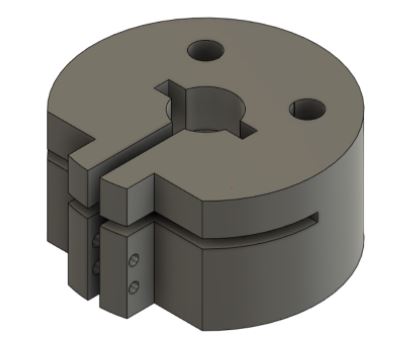
| + | The center hole tightens around the shaft using the screws on the side, while the 2 non centric holes are to hold M8 screws that would connect to the stem, thus turning the stem and bike fork. The vertical and horizontal slit cuts are to allow the shaft collar to bend when tightening when clamping to motor shaft. The center hole has a diameter of 0.5 inches on the bottom and a diameter of 0.625 inches. This is so, when flipped over, the bottom circle cut can cover the hexagonal screw head on the bmx bike stem. | ||
| + | |||
| + | One major challenge of designing the collar was designing it in a way that was possible for it to be made through machined stock, as the provided collar had holes drilled into a non flat surface for the screws to be inserted. The work around for that ended up being to just completely cut into the circle using the mill to create a right angle to serve as the surface to drill and tap holes into. This will allow for a drill to cleanly cut into the sides of the collar when the top and bottom of the collar are clamped by the vice. In terms of other machining, the center hole would use the lathe, the non-center holes would be done using the mill, and the thin cuts would be done using the band saw. | ||
==Camera Assembly== | ==Camera Assembly== | ||
| Line 69: | Line 85: | ||
The camera seat acts as a point of securement for the camera on the new bike and as such needs to fulfill the goals of interfacing with the variable angle and variable height components within the body assembly. This requires the camera seat to fit onto the assembly bar detailed below. The design allows the camera seat to fulfill these goals by clamping directly to the connections at the end of the connecting bars to which the assembly bar would be placed in between. These bars are specifically designed to uphold the design requirements of the camera: needing to have 20% of its field of view above the horizon in the default position and enabling variable height. | The camera seat acts as a point of securement for the camera on the new bike and as such needs to fulfill the goals of interfacing with the variable angle and variable height components within the body assembly. This requires the camera seat to fit onto the assembly bar detailed below. The design allows the camera seat to fulfill these goals by clamping directly to the connections at the end of the connecting bars to which the assembly bar would be placed in between. These bars are specifically designed to uphold the design requirements of the camera: needing to have 20% of its field of view above the horizon in the default position and enabling variable height. | ||
===Head Tube Frame Bracket=== | ===Head Tube Frame Bracket=== | ||
| − | The head tube clamp was made from 2 machined pieces of aluminum. Both have a large curvature on one of their faces in order to interface with the bike. Similar to the frame brackets, the inner curved surface of the grips has a piece of rubber to ensure that the clamps do not slip. The two pieces are compressed together through the use of four 5M 20mm screws. The significance of the Head Tube clamp is in allowing for variable angles to be achieved through its interfacing with the assembly bar. | + | The head tube clamp was made from 2 machined pieces of aluminum. Both have a large curvature on one of their faces in order to interface with the bike. Similar to the frame brackets, the inner curved surface of the grips has a piece of rubber to ensure that the clamps do not slip. The two pieces are compressed together through the use of four 5M 20mm screws. This differs with the frame brackets and the motor connection point, the head tube frame does not have a 14mm bolt going through the bracket and head tube as it would prevent the steering tube within the head tube from being able to turn and steer the bike. The significance of the Head Tube clamp is in allowing for variable angles to be achieved through its interfacing with the assembly bar. |
[[File:HeadFrameBracketRender.png|200px|thumb|left|Head Tube Bracket]] | [[File:HeadFrameBracketRender.png|200px|thumb|left|Head Tube Bracket]] | ||
| + | |||
===Assembly Bar=== | ===Assembly Bar=== | ||
[[File:assemblyBarRender.png|200px|thumb|right|Assembly Bar]] | [[File:assemblyBarRender.png|200px|thumb|right|Assembly Bar]] | ||
| Line 77: | Line 94: | ||
==Battery Assembly and Rack== | ==Battery Assembly and Rack== | ||
| + | [[File:FullWithBatteryHolder.png|200px|thumb|left|Full render with battery holder]] | ||
| + | It was decided that the bike’s battery would rest mounted above the back wheel (instead of on either side of the bike or at the front of the bike). More specifically it was decided that the battery would be mounted on the back pannier rack, which is above the back wheel. | ||
| + | |||
| + | Naturally, we needed to design some sort of interface which used the geometry of the battery and the geometry of the top face of the pannier rack to secure the battery. We decided on an acrylic panel. This panel would have screws running through it that connect to the bottom face of the pannier rack and also interfaces with the battery while passing through the panel, the panel acting as a sort of buffer. | ||
| + | |||
| + | The acrylic used was leftover from the construction of the electric panels, specifically the white .25” acrylic panel purchased from McMaster-Carr. After one prototype we had finished a final design for the battery panel, a 28cm by approximately 10.9cm filleted panel with holes located along the main axis of the panel and where other components of the battery would attach to the panel. This design has not yet been constructed, but it has been sent to the RPL for laser cutting and has also been added to the combined CAD. | ||
| + | |||
| + | At present there is no finished design or external component that protects the battery from damage in the event of a fall, however simply shielding the battery with the foam it was packaged in when we received it has been entertained as a legitimate possibility. | ||
| + | |||
| + | The pannier rack which holds the bike’s battery has yet to be constructed in the combined CAD, in the meantime a publicly available 3D model for a pannier rack has been added to the combined CAD. | ||
| + | |||
| + | =Cosmetics= | ||
| + | ==Paint== | ||
| + | [[File:BikePainted.jpg|200px|thumb|left|New Bike Post-Paint]] | ||
| + | The color of paint used on the bike frame and fork is Coventry red, and was chosen for its similarities to Cornell Red. The spray paint used was purchased from spraybikes.us, and applied using first a zinc-based primer, then the paint, and then finally treated with a coating of gloss, all purchased from spraybikes.us. | ||
| + | |||
| + | It must be noted that all paint and paint accessory applications were conducted in the ELL’s paint room with proper personal protective equipment on. | ||
| + | |||
| + | ==Decals== | ||
| + | For the purpose of aesthetics, we decided that we would put a few decals on both the bike’s main acrylic panels and the bike frame. To do this we used an online service called doityourselfelttering.com, a company that prints custom bike decals. The specific type we got was ‘standard calendered vinyl’. We had three stickers we wanted to incorporate, one that says “Cornell Autonomous Bicycle”, one that says, “Bichael (Michael.. but bike)”, and one that says “A Special Thanks to Karen & Ed Thomas”. The Thomas’s are an Ithaca couple who sheltered the 2021 Mechanical Subteam during a partial evacuation of campus due to a public safety matter. These decals came with three blue application squeegees at only an additional charge of $2.25. doityourselflettering.com appears to be an excellent choice for decals with appropriate pricing, well-performing products, and excellent customer service. More decals have been ordered, and their application to the bike will likely come sometime after all the electrical components have been mounted. | ||
=Bike Details= | =Bike Details= | ||
[[File:Bike_dimensions.png|200px|thumb|right|General Dimensions]] | [[File:Bike_dimensions.png|200px|thumb|right|General Dimensions]] | ||
| − | [[File: | + | [[File:Frame.jpg|200px|thumb|left|The original frame]] |
| − | + | ==Frame== | |
The frame is a ***cm KTM Trento with serial number ******. | The frame is a ***cm KTM Trento with serial number ******. | ||
| − | + | ==Wheels== | |
The wheels are 27 inches in diameter. The planned tires will be 27-inch road bike tires. General dimensions for the bike can be found in the image to the right. | The wheels are 27 inches in diameter. The planned tires will be 27-inch road bike tires. General dimensions for the bike can be found in the image to the right. | ||
Latest revision as of 02:04, 10 December 2021
This is the next platform of the Cornell Autonomous Bicycle Team. It is intended to be a more stable, reliable, and versatile platform than The Old Bike. The bike is nearly complete with completion expected in Spring 2022.
LAST UPDATE - FALL 2021
Contents
Design Overview
The main objective for the new bicycle was to prevent the need for welding and other permanent structures compared with the Old Bike. To do this, we've adopted a modular design approach with all the added components of the bicycle to allow for re-design opportunities of different parts and fixtures present on the bike. This approach will extend the usefulness of the platform for years to come.
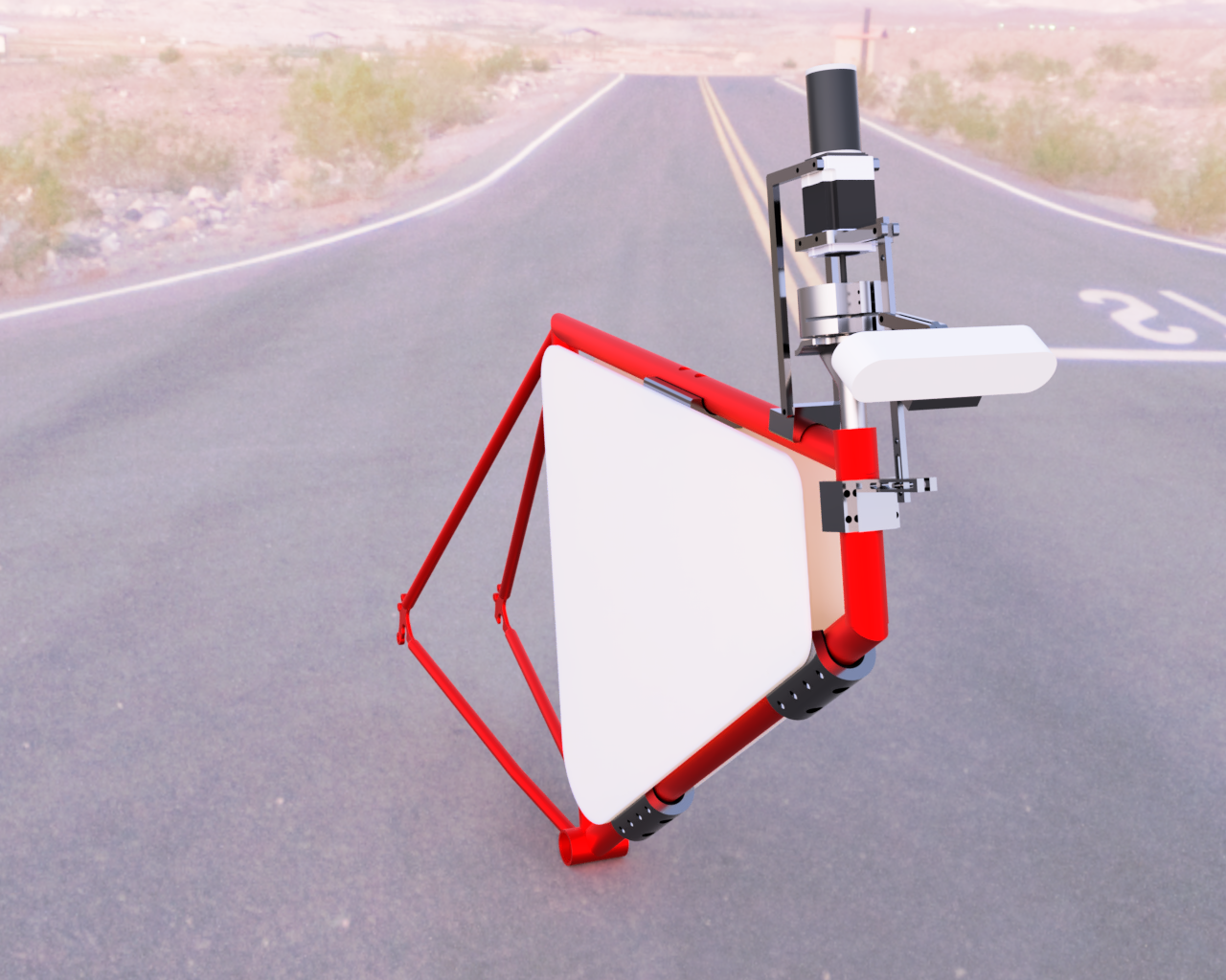
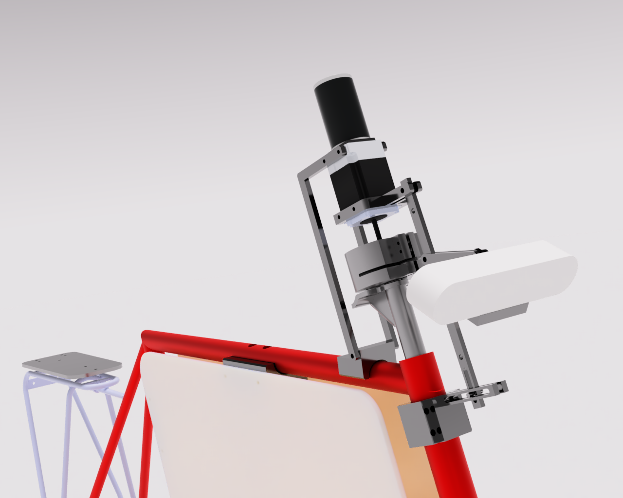
The final design for the bike can essentially be split up into two major regions: the Brain and the Body. This split is defined by the connection between different components. The “Brain” sits around the diamond of the bike frame while the “Body” is situated around and extending outward from the head tube. This distinction, though somewhat ironic considering the relative locations of the regions, is useful because it lends itself to let us think and design more locally.
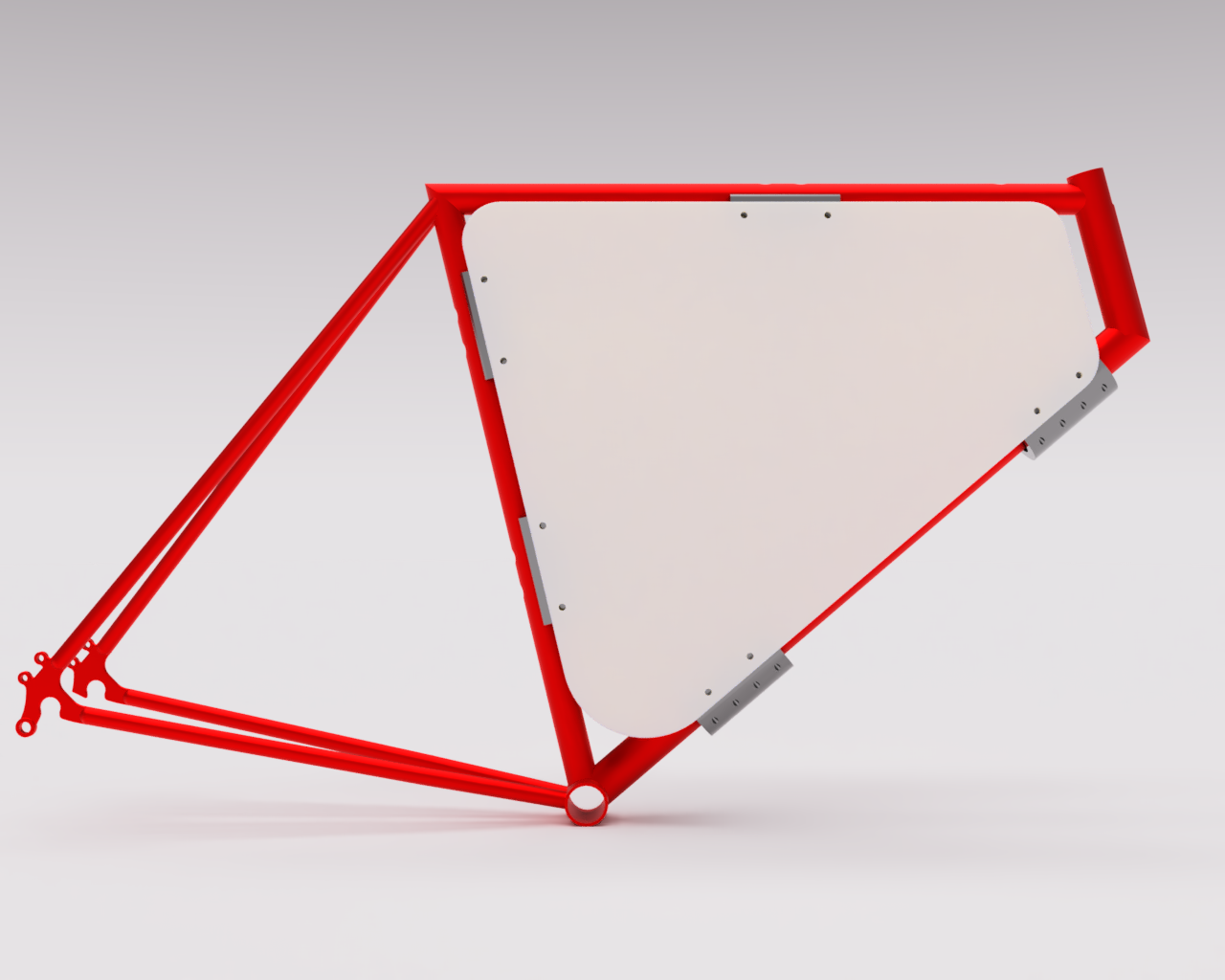
The “Brain” is defined by its contents: the electronics. It is composed of 4 clamp-like components, 2 sheets of acrylic, and 2 panels for the electronics to sit. The clamp-like components connect to the edges of the bike diamond in order to give the acrylic sheets points to connect to in order to enclose the frame. The electronics, once situated onto their corresponding panels, will be attached with velcro to the acrylic sheets. Similar to the brain, the “Body” is defined by its function, in this case, the handling of actuation and vision on the bike. The body is composed of 2 main intertwining assemblies. One centered around the motor and the other around the camera.
Mechanical Components
Frame Brackets
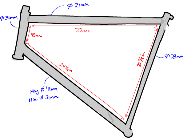
The frame brackets act to suspend the panes that will encase the electronics in the center of the bike. Each frame bracket is designed to adhere to a specific portion of the bike's geometry.
As of Fall 2021, the frame brackets have been mounted.
Top Frame Bracket
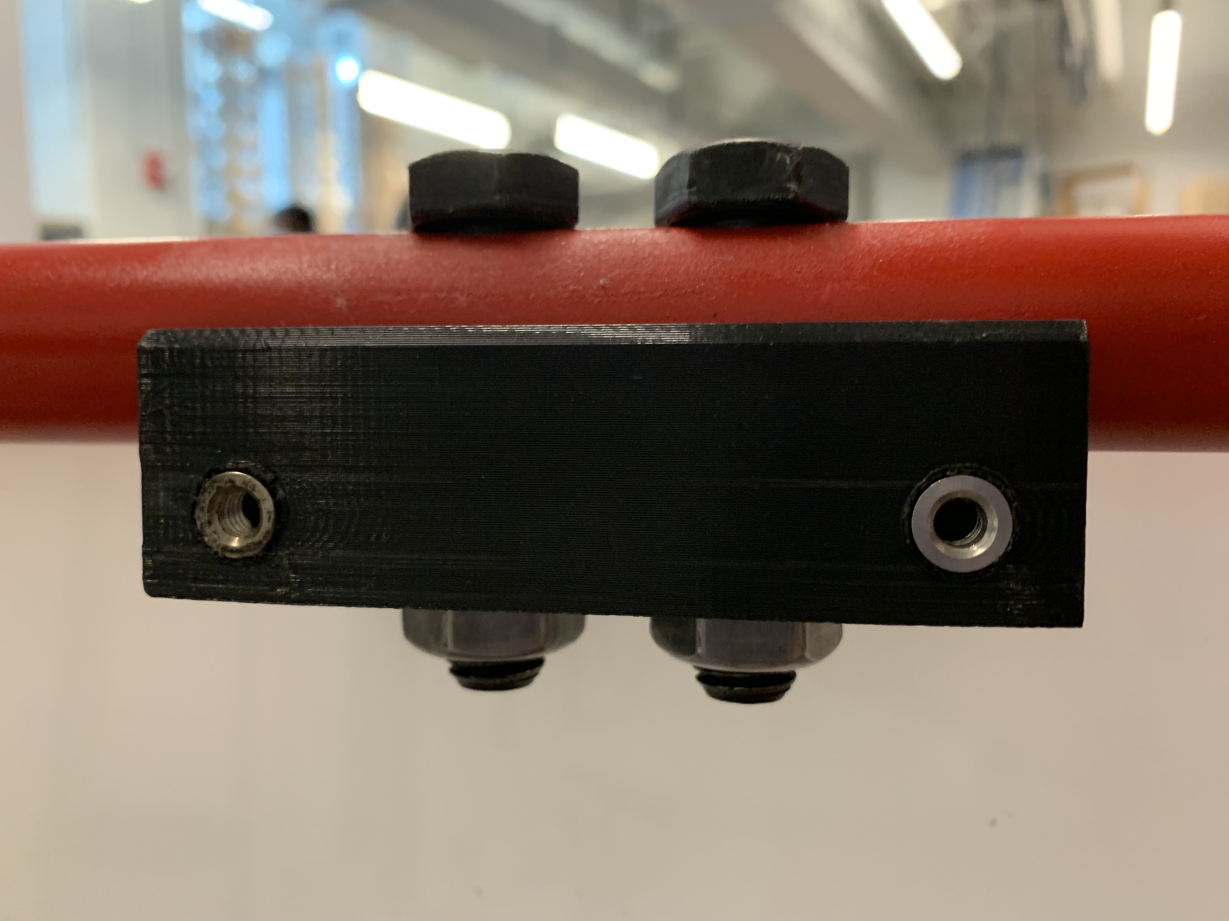
The top frame joint is specifically is made for the rounded surface on the top tube and seat tube of the bike. It is made up of 4 major components: the base, a piece of rubber that sits between the bike and the base, two hex head screws, and two nuts to match.
Near the bottom edge of the part, there are four threaded holes (two on either side) that indicate where the part will attach to the acrylic panes. The rubber sits directly on top of the curved edge of the aluminum. It is meant to provide grip strength so that the component does not slip out of place. There are two 9/16" holes on top that propagate through the entire design and the bike frame itself that make space for the bolts and nuts to compress all the components to the bike frame.
The top frame brackets were 3d printed with high amounts of infill. The top brackets were originally intended to be machined out of aluminum but the large diameter hole at the parts center proved too large to drill with the means available to us. To that end, the final design uses threaded inserts, that were heated with a soldering iron and slipped into the intentionally widened holes of the top frame bracket. The results of this can be seen in the accompanying image.
Bottom Frame Bracket
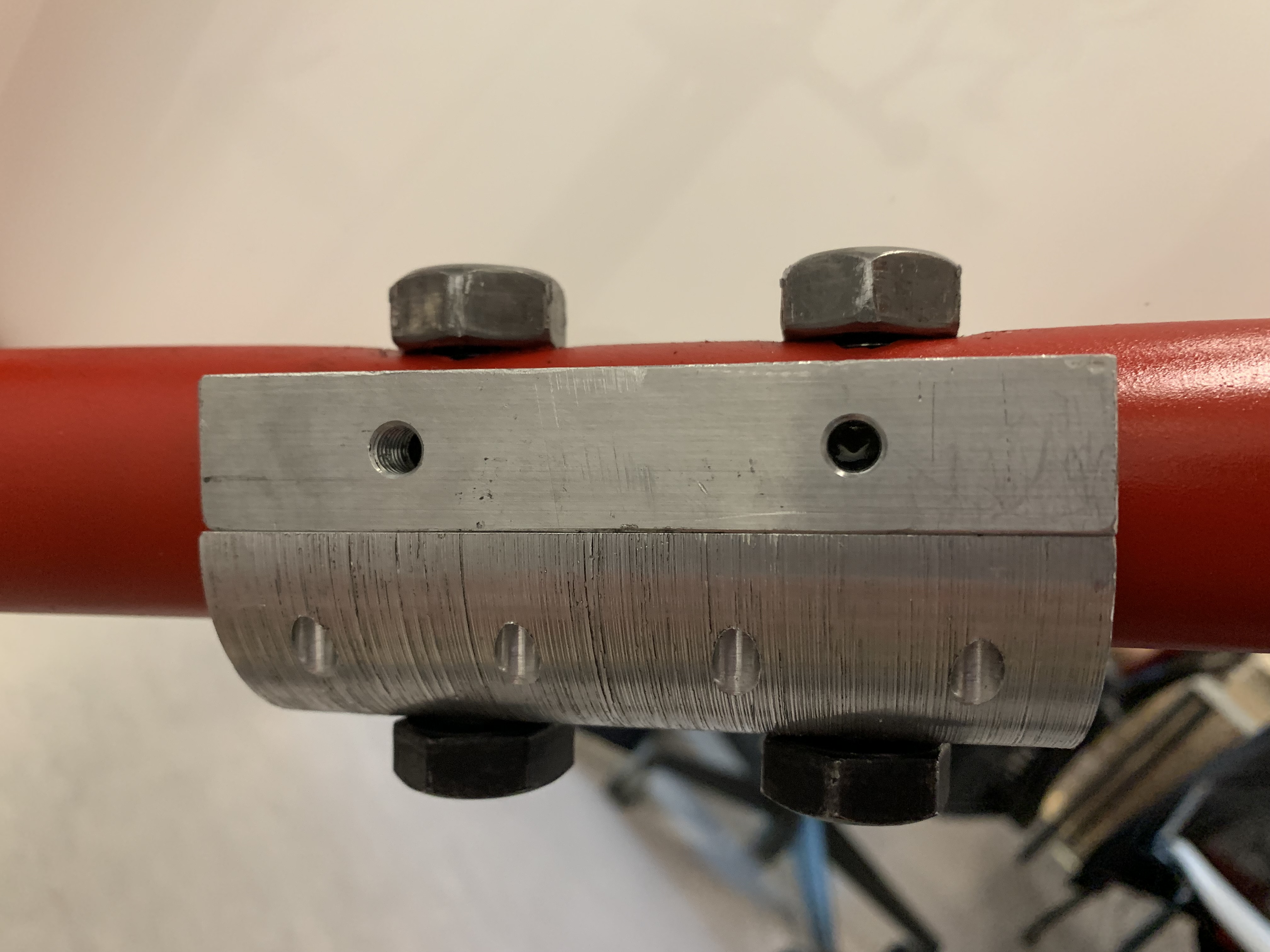
The bottom frame joint has an identical function as the top frame joint. However, the bottom frame joint's geometry differs from it because the cross-section of the bottom tube is elliptical. This presented a unique design challenge that we had to workaround. We ended up settling on an idea that combines 4 different parts together: 2 flat plates, a hemispherical piece, and rubber.
In order to match the elliptical shape of the bottom tube, these parts are screwed together as seen in the image. There exist larger holes on the surface of the hemispherical piece to make room for screw heads, and there exist threaded holes that cut through half of the flat pieces. Near the top edge of the flat plates, there are threaded screw holes for attachment to the clear planes. The rubber again acts as a way to grip the components to the frame and prevent slip. Just like the top frame joint, there are two 9/16" holes made in both the frame, rubber, and hemispherical piece to make room for the bolts and nuts to compress the system to the bike frame. 2 Bottom frame joints will be used to hold the panes.
- Someone add about machining issues?*
Electronics Panel
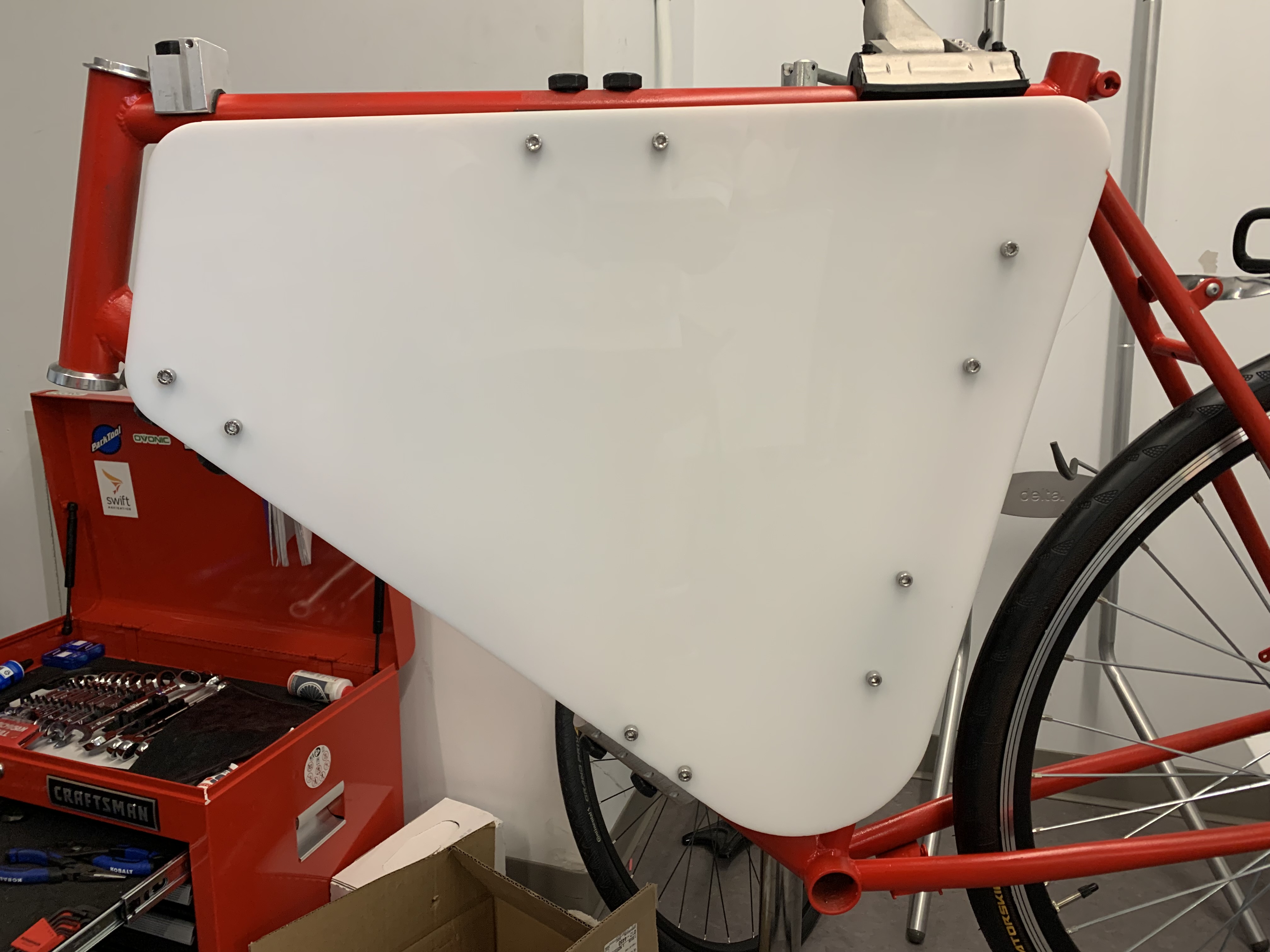
As stated prior, two acrylic sheets will be sitting in between the frame of the bicycle. The panels will be supported by the frame brackets. In between the pieces of acrylic the electronics will be mounted with the use of velcro. Velcro was chosen because of its shear strength and relative ease of placement.
The panels were laser-cut from 24"x24" pieces of acrylic. While the shape was lasercut, the holes for the mounting points were self-drilled. They are self-drilled because of the inaccuracy of the measured dimensions received for the bike and the frame brackets. Slight differences from the original models caused the prototypes for the acrylic to be off by millimeters at a time, lowering our confidence that laser cutting the holes would actually result in holes that lined up with the actual configuration of the frame brackets.
As of Fall 2021, the acrylic panels have been mounted.
Front Motor Assembly
Motor Connection point
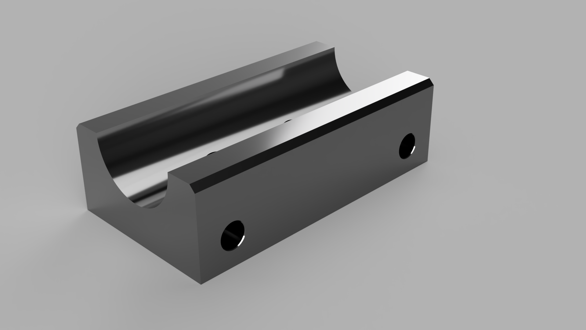
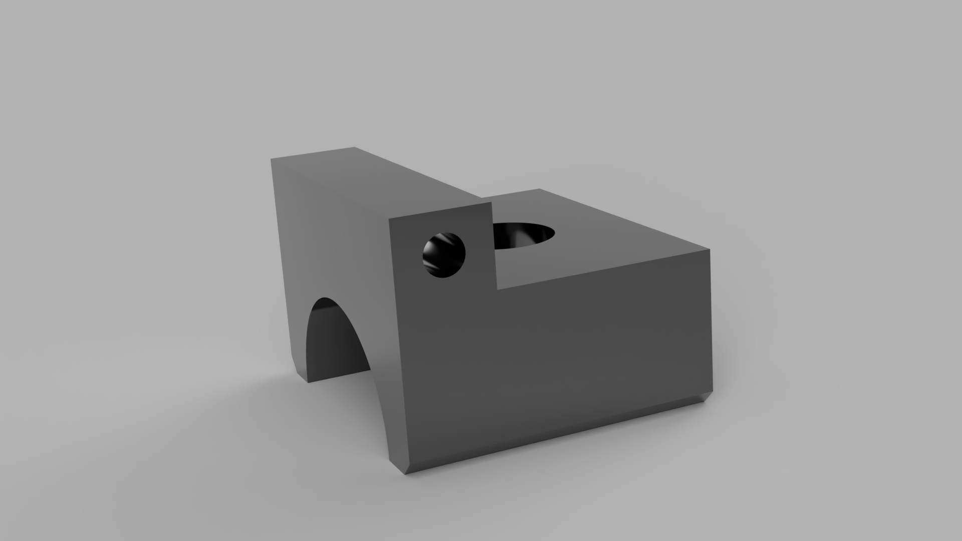
The Motor Connection as seen below is the main mechanism that connects the motor encasement legs to the top tube of the frame, thus securing the motor indirectly to the frame. The motor connection has a similar design to the frame brackets in how it is secured to the top tube of the frame: same diameter aluminum semicircle that has a layer of thin rubber attached onto the inside. The center of the z axis of the half-pipe has a 14 mm hole to fit a bolt that would serve as a fixed joint to prevent all possible movement.
For machining, similar to the top tube frame, in order to create the half pipe hole, we have to make a full hole and then cut the entire part in half to create the semicircle. The top is machined with a 14mm hole as mentioned above. Another minor machining adjustment that was not on the cad drawing was to create a small crevice into the top lip of the part, on the side where the 14 mm hole is. This is to fix a (compliance) problem where the bolt couldn't be screwed fully in due to the lip. The sides of the top lip are threaded in m4 so the motor enclosure legs will be clamped by screw to secure them.
Motor Enclosure
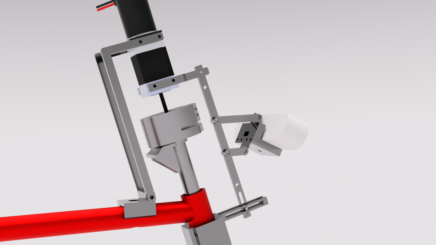
The Motor Enclosure acts as the mechanism to secure the bike relative to the frame and the camera mount. The top two arms are large L shaped bars that connect to the motor connection point. They are L's instead of straight lines to the Motor Connection point to give room for the motor shaft collar as it has a very large overall diameter. The bottom component of the motor enclosure is shaped similarly to a football goal post with the two prongs attaching to the left and right sides of the motor. The singular end prong sticks out in the front with a small parallel fork at the end to fit the camera assembly bar. This is so the end of the bottom components also acts as the hinge support enabling the rotation of the assembly bar, thus allowing the camera angle to change.
In terms of machining all the parts follow the machining drawing as they are all comprised of right angular cuts. All of the holes are not tapped or threaded as they just serve to allow screws pass through. The motor and the motor connection point are the tapped components the secure the screws, while the camera assembly joint will be secured with a screw and hex nut.
Motor shaft collar
The center hole tightens around the shaft using the screws on the side, while the 2 non centric holes are to hold M8 screws that would connect to the stem, thus turning the stem and bike fork. The vertical and horizontal slit cuts are to allow the shaft collar to bend when tightening when clamping to motor shaft. The center hole has a diameter of 0.5 inches on the bottom and a diameter of 0.625 inches. This is so, when flipped over, the bottom circle cut can cover the hexagonal screw head on the bmx bike stem.
One major challenge of designing the collar was designing it in a way that was possible for it to be made through machined stock, as the provided collar had holes drilled into a non flat surface for the screws to be inserted. The work around for that ended up being to just completely cut into the circle using the mill to create a right angle to serve as the surface to drill and tap holes into. This will allow for a drill to cleanly cut into the sides of the collar when the top and bottom of the collar are clamped by the vice. In terms of other machining, the center hole would use the lathe, the non-center holes would be done using the mill, and the thin cuts would be done using the band saw.
Camera Assembly
The main requirements for the camera assembly were to have a modifiable angle of roughly ~10 degrees, for the camera in its default position to have 20% of its field of view be above the horizontal, for the camera height to be editable, and for the camera to sit a foot above handlebar height. With a field of view of 56 degrees, 20% field of view equates to the camera sitting at an angle of 26.8 degrees below the horizontal. In the full assembly, this results in a range of 16.8 to 36.8 degrees for the positioning of the camera. These points were easily achieved with the final design of the camera assembly which featured a seat and adjustable framework that allowed for easy manipulation of the height and angle of the camera.
Some camera components have started being machined, the rest are slated to be completed Spring 2022.
Camera Seat
The final design of the camera seat consists of 6 parts: 4 connecting bars and 2 small machined blocks of aluminum. The first rectangle of aluminum is used as an anchor for the camera itself. It has a ¼” hole near its center to make room for a bolt to attach the piece to the camera’s threaded bottom. The second rectangle of aluminum serves to connect the clamping components (connecting bars) to the system. Similar length bars are paired together and clamped, by way of nut and bolt, to the top of the upright piece. In addition, the upright piece also has a squared hole in order to make room for the USB of the camera. This piece is then connected to the first piece of aluminum by 4 screws.
The camera seat acts as a point of securement for the camera on the new bike and as such needs to fulfill the goals of interfacing with the variable angle and variable height components within the body assembly. This requires the camera seat to fit onto the assembly bar detailed below. The design allows the camera seat to fulfill these goals by clamping directly to the connections at the end of the connecting bars to which the assembly bar would be placed in between. These bars are specifically designed to uphold the design requirements of the camera: needing to have 20% of its field of view above the horizon in the default position and enabling variable height.
Head Tube Frame Bracket
The head tube clamp was made from 2 machined pieces of aluminum. Both have a large curvature on one of their faces in order to interface with the bike. Similar to the frame brackets, the inner curved surface of the grips has a piece of rubber to ensure that the clamps do not slip. The two pieces are compressed together through the use of four 5M 20mm screws. This differs with the frame brackets and the motor connection point, the head tube frame does not have a 14mm bolt going through the bracket and head tube as it would prevent the steering tube within the head tube from being able to turn and steer the bike. The significance of the Head Tube clamp is in allowing for variable angles to be achieved through its interfacing with the assembly bar.
Assembly Bar
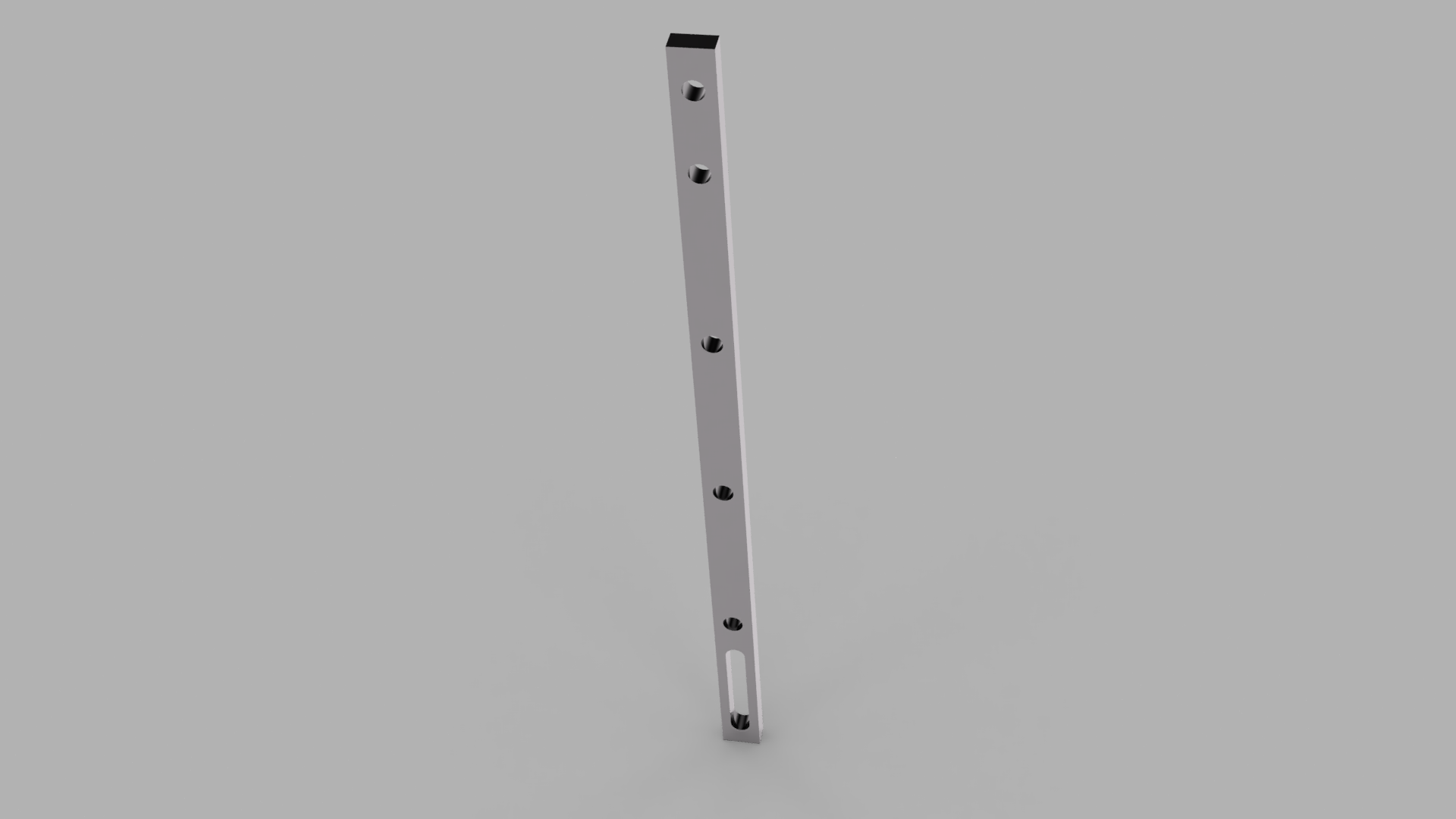
The assembly bar is secured by one of the motor attachments as mentioned earlier. A clamp is attached to the top of the head tube. This clamp has on it an extruded piece of aluminum with its own slot. Sliding the assembly bar’s slot up or down relative to the slot of the head tube bracket allows for different angles to be achieved. This angle is able to be changed +/- 10 degrees from its origin. The assembly bar has multiple points that the connecting bars can connect to on the assembly bar. This allows the camera to be moved up and down along these holes and thus change the height of the camera. The assembly bar itself is positioned at a 15-degree angle from vertical in its default state and thus the computation for the length of the connecting bars reflects this.
Battery Assembly and Rack
It was decided that the bike’s battery would rest mounted above the back wheel (instead of on either side of the bike or at the front of the bike). More specifically it was decided that the battery would be mounted on the back pannier rack, which is above the back wheel.
Naturally, we needed to design some sort of interface which used the geometry of the battery and the geometry of the top face of the pannier rack to secure the battery. We decided on an acrylic panel. This panel would have screws running through it that connect to the bottom face of the pannier rack and also interfaces with the battery while passing through the panel, the panel acting as a sort of buffer.
The acrylic used was leftover from the construction of the electric panels, specifically the white .25” acrylic panel purchased from McMaster-Carr. After one prototype we had finished a final design for the battery panel, a 28cm by approximately 10.9cm filleted panel with holes located along the main axis of the panel and where other components of the battery would attach to the panel. This design has not yet been constructed, but it has been sent to the RPL for laser cutting and has also been added to the combined CAD.
At present there is no finished design or external component that protects the battery from damage in the event of a fall, however simply shielding the battery with the foam it was packaged in when we received it has been entertained as a legitimate possibility.
The pannier rack which holds the bike’s battery has yet to be constructed in the combined CAD, in the meantime a publicly available 3D model for a pannier rack has been added to the combined CAD.
Cosmetics
Paint
The color of paint used on the bike frame and fork is Coventry red, and was chosen for its similarities to Cornell Red. The spray paint used was purchased from spraybikes.us, and applied using first a zinc-based primer, then the paint, and then finally treated with a coating of gloss, all purchased from spraybikes.us.
It must be noted that all paint and paint accessory applications were conducted in the ELL’s paint room with proper personal protective equipment on.
Decals
For the purpose of aesthetics, we decided that we would put a few decals on both the bike’s main acrylic panels and the bike frame. To do this we used an online service called doityourselfelttering.com, a company that prints custom bike decals. The specific type we got was ‘standard calendered vinyl’. We had three stickers we wanted to incorporate, one that says “Cornell Autonomous Bicycle”, one that says, “Bichael (Michael.. but bike)”, and one that says “A Special Thanks to Karen & Ed Thomas”. The Thomas’s are an Ithaca couple who sheltered the 2021 Mechanical Subteam during a partial evacuation of campus due to a public safety matter. These decals came with three blue application squeegees at only an additional charge of $2.25. doityourselflettering.com appears to be an excellent choice for decals with appropriate pricing, well-performing products, and excellent customer service. More decals have been ordered, and their application to the bike will likely come sometime after all the electrical components have been mounted.
Bike Details
Frame
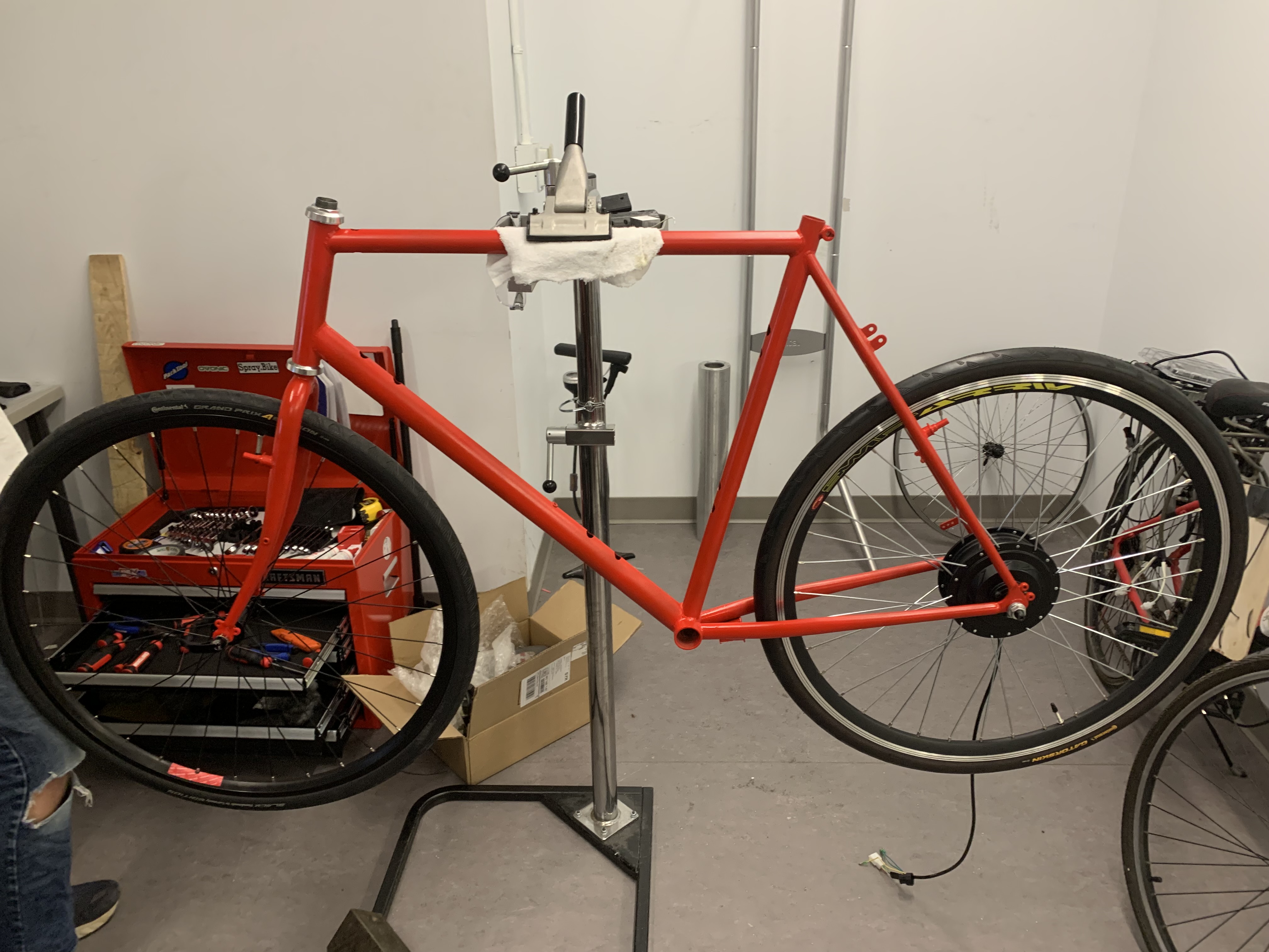
The frame is a ***cm KTM Trento with serial number ******.
Wheels
The wheels are 27 inches in diameter. The planned tires will be 27-inch road bike tires. General dimensions for the bike can be found in the image to the right.
